- PRODUCTS
ApplicationFormatApplicationFormatApplicationFeatured


NEWS
News & Events
The Road to Robust 5G: A Deep Dive into Base Station Power Supply Reliability Challenges
05
Dec
Dec. 05, 2025

Cincon offers highly reliable DC-DC solution & AC-DC solution for 5G base stations, conquering harsh outdoor environments with fanless cooling technology.
In a world swept by 5G networks, we enjoy high-speed, low-latency mobile internet experiences. Behind this transformation are countless quietly operating base stations. One of the core components within these stations—the Remote Radio Unit (RRU)—is truly the "cornerstone of network coverage." The RRU"s journey from inception to widespread adoption is, in itself, a technical revolution designed to overcome the drawbacks of traditional integrated base stations.
I. From Integrated to Distributed: The Birth and Technical Advantages of the RRUTraditional "integrated base stations" concentrated all processing and radio frequency (RF) units in an equipment room at the base of the tower,transmitting signals to the antenna on the tower top via long feeder cables.This architecture suffered from several critical weaknesses: 1. Massive Feeder Loss: Signal power loss could exceed 60% during transmission through feeder cables tens of meters long. 2. Alarming Energy Consumption: To compensate for feeder loss , the base station had to provide significantly higher transmit power, causing overall energy consumption to skyrocket, easily exceeding 3000 watts at a multi-band site. 3. Heat Dissipation Challenge: High-power equipment concentrated in the equipment room created immense cooling pressure. 4. Inability to Meet 5G Demands: MIMO (Multiple-Input Multiple-Output) technology requires multiple transmit channels, which integrated base stations struggled to accommodate. |
Figure 1: A Macro Base Station RRU & BBU |

The RRU Solution: The RF unit was "liberated" from the equipment room and mounted directly on the tower, right next to the antenna. This change brought about fundamental improvements:
‧ Near-Zero Feeder Loss: The signal is "within reach," and almost all energy is used for radiation, doubling efficiency.
‧ Significantly Reduced Total Power Consumption: Eliminating the need to compensate for feeder loss drastically cuts overall energy consumption.
‧ Flexible Deployment and Multi-Antenna Support: Provides the perfect hardware foundation for 5G"s massive MIMO technology.
II. The Extreme Challenge: The RRU Power Supply"s "Hellish" Operating Environment
However, moving sophisticated electronic equipment from a climate-controlled room to a tower exposed to the elements imposes extremely stringent requirements on its power module. The design of the RRU power supply is a battle against the extreme environment:
1. Severely Restricted Space: Space on the tower is precious, demanding that the power supply be highly miniaturized with high power density.
2. Unparalleled High Efficiency: Any efficiency loss turns into heat, which accumulates in the sealed space. Every 1% increase in efficiency means a significant reduction in temperature rise and a massive boost to system reliability.
3. "Fanless" Cooling and Superior Thermal Management: Tower-mounted equipment cannot use fans (prone to damage, increased maintenance costs). It must rely on natural convection and efficient thermal design to rapidly transfer internal heat to the external casing for dissipation.
4. Wide Range, High Ambient Temperature: Must operate reliably and stably long-term in ambient temperatures ranging from -40°C to +45°C, or even higher.
5. High Reliability Requirements: This mandates a pursuit of "zero defects" in the power supply"s design, component selection, and manufacturing.
III. Cracking the Core Problems: CINCON Power"s Technical Breakthrough
To meet the extreme demands of RRU deployment, Cincon has achieved a technical breakthrough across several key dimensions:
1. Ultimate Efficiency to Reduce Heat Loss at the Source. Given the sealed internal space, heat dissipation is the primary difficulty. Any efficiency loss in the power supply directly translates into heat, threatening system stability.
‧ CINCON Solution: Employing advanced LLC resonant topology and introducing next-generation semiconductor power components like MOSFETs and SiC (Silicon Carbide) to achieve efficiency exceeding 94.5%. This means less energy is wasted as heat, fundamentally reducing system cooling pressure.
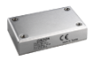
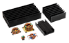
2. The Art of Superior Thermal Management: Enabling Stable "Fanless" Operation Since the equipment cannot rely on fan cooling, Cincon"s baseplate-cooled, "fanless design" is the industry standard.
CINCON Solution:
‧ Optimizing internal layout through precise thermal simulation, tightly coupling main heat sources (such as power MOSFETs and magnetic components) with the carefully designed aluminum alloy heat-dissipating enclosure.
‧ Utilizing high-thermal-conductivity insulating materials internally to build an efficient heat transfer path, ensuring heat is rapidly and uniformly dissipated into the environment.
‧ Selecting components that are wide-temperature and highly reliable, and offering a complete product plan that includes slim-profile and high-ambient-temperature/high-reliability products.
|
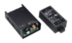
Figure 2: Typical Open-Frame Cooling |
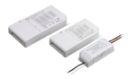
Figure 3: CINCON Baseplate-Cooling |


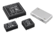
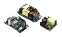
IV. The Open Frame with Baseplate-Cooled Series
These series offer various major product families: 130W, 150W, 200W, 260W, 300W, 400W, and 500W. All feature high operating temperatures, limited space suitability, fanless operation, and long-life, high-efficiency power. We highlight the 300W, 400W, and 500W series here.
‧ Over Temperature Protection
‧ PS On/Off Remote Control
‧ Power Good & Power Fail Signal
‧ +5V Stand-by, 12V Fan Output
‧ Low Inrush Current, with CFM500S as low as 8.5A
‧ The Cincon CFM500S also offers Parallel (Active Current Sharing) and PMBus options.
| Series | Power (W) |
Input Voltage | Output Voltage (Vdc) |
Efficiency | I/O Isolation (Vac) |
Dimension (inch) |
| CFM300S | 300 | 90-264 Vac 120-370 Vdc |
12、24、36、48 | 94% | 3000 | 3”x 5” Compact Size |
| CFM400S | 400 | 80-264 Vac | 12、18、24、 36、48、54 |
94% | 4000 | 3”x 5” Compact Size |
| CFM500S | 500 | 80-264 Vac | 12、18、24、 28、 30、36、48 |
94.5% | 4000 | 3”x 5” Compact Size |
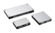
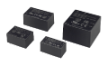
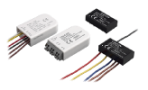
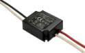
V. Pushing the Boundaries of Innovation: The New Cincon LFM Series
In the continuously evolving power supply industry, Cincon constantly pushes the boundaries of innovation. We introduce the LFM series, designed specifically for harsh operating environments, featuring an ultra-slim profile and excellent high-temperature performance. The next-generation LFM series (Low Profile, 1 inch height) sets a new benchmark for efficiency and reliability.

| Series | Power (W) |
Input Voltage | Output Voltage (Vdc) | Eff | I/O (Vac) |
Dimension (inch) |
| LFM200S | 200 | 85-264 Vac 115-370 Vdc |
12、15、24、28、 30、36、48、54、 |
94% | 4250 | 2.28”x 3.09”x 1” |
| LFM300S | 300 | 85-264 Vac | 12、15、24、 28、30、48、54、 |
94% | 4250 | 2.28”x 4.09”x1” |
| LFM420S | 420 | 85-264 Vac 120-370 Vdc |
12、15、24、28、 30、36、48、54、 |
94.5% | 4250 | 3.29”x 5.09”x 1” |
| LFM550S | 550 | 85-264 Vac 115-370 Vdc |
12、15、24、28、 30、36、48、54、 |
94% | 4250 | 3.29” x 5.09”x 1” |
Please refer to the official website datasheet for detailed parameter specifications.
VI. Small Cells: The Vast Application Prospect in 5G Deep Deployment
In the 5G era, as the frequency band moves further up (higher frequency, shorter wavelength), signal attenuation increases significantly when encountering obstacles, leading to a smaller coverage area for macro base stations. At the same time, hot zones require a thousandfold increase in capacity and demand a higher network experience. This has led to capacity and coverage shortages appearing early in 5G deployment.
Small cells offer the advantage of precise coverage supplements and are the most effective way to expand capacity through frequency reuse. Therefore, the demand for small cells is urgent in 5G and will continue into 6G, requiring large-scale deployment of a "macro-small combination" to solve coverage and capacity expansion issues.

Figure 5: Key Characteristics of Small Cells
This urgency imposes even stricter requirements on the supporting power supply—how to achieve efficient, stable, and fanless cooling and power delivery within extremely limited space has become a critical industry challenge. Cincon Electronics is deeply committed to fanless cooling technology, specializing in developing high-reliability AC/DC and DC/DC power solutions for harsh environments. Leveraging our market-proven product performance and system adaptability, we have built a product line that covers all power supply scenarios for base stations, providing solid support for base station equipment construction.
| Application | Types | Reference Models |
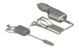
| 5G Small Cell station | AC-DC Fanless Power | CFM500S480 &LFM550S480&PDF700S480 |
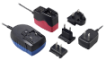
| 5G POE | AC-DC Adapter | TRH220A480 |
| DC-DC Quarter Brick Converter | CQB75W8-36S12 | |
| 5G Router Power | DC-DC Converter | EC7BW18-72S12 ,ECB40W18-72S12 |
| 5G External Power Source | DC-DC Converter (turn-key solution with Din-Rail plug) |
EC7BW18-72S12-EDRT ,ECB40W18-72S05-ECRT |
| 5G Repeater Power | DC-DC Quarter Brick Converter | CQB150W-48S28 |
| 5G Base Station | AC-DC Fanless Power | LFM300S480C ,CBM300S480 |
| DC-DC Half Brick Converter | CQB150W8-36S05 ,CQB150W8-36S12 | |
| 5G Network Densification | DC-DC Full Brick Converter | CFB600-48S48 |
| 5G Telecom Rectifier | DC-DC Half Brick Converter | CHB300-300S12 |
Facing the Future:
The base station power supply is no longer a simple energy conversion unit; it is critical infrastructure that ensures the availability and reliability of the entire mobile network. Cincon will continue to innovate in the power sector, providing customers with more efficient, more compact, and smarter power solutions to help global operators build greener, more reliable 5G and future 6G networks.
Contact Cincon for more support:sales@cincon.com