- 產品介紹
機型特色產品


最新消息

新聞與活動
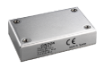
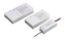
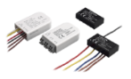
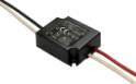
CFM500M/S Series Baseplate Cooling & Cover Power Supply
10
Sep
Sep 10, 2021

Never Stop Improving Switching Power Supplies:
With the evolution of technology and product design in the fields such as industrial, telecom, medical, and consumer electronics, the demand of high-efficiency and downsized power supplies with functions like digital control, multitasking has been increasing. The efficiency and power density have the direct influence on temperature inside the end-user system. For that reason, Cincon has been dedicated to developing the high-quality power supplies with a baseplate-cooling design because heat dissipation improvement is always an ongoing mission. In this case, Cincon has released a series of baseplate-cooling and fanless power supply solutions due to the conduction characteristic. Today we are going to show you the CFM500M/S series which also have the optional case version.
Advantages of CFM500 Power Supply:
The structure of CFM500M/S is PFC+LLC with universal input voltage of 80 to 264Vac and the high efficiency is up to 94.5%, leading to less power loss and generation of heat. The CFM500M/S series have output power of 500W with 3” x 5” and output voltages of 12Vdc, 18Vdc, 24Vdc, 36Vdc, 48Vdc. The CFM500M/S also have the distinctive feature of low inrush current, lowering the impact on surrounding application such as fuse, switch, etc. and making the system operate stably.
In addition, CFM500M/S series offer various features and full protections:
• PS On/Off Remote Control
• Power Good & Power Fail Signal
• +5V Stand-by, 12V Fan Output
• OTP, OCP, Continuous Short Circuit Protection (Auto-Recover)
• Over Voltage Protection
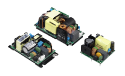
The CFM500S has the safety approvals of IEC/UL/EN 62368-1 and meets the EMC standard of light/heavy industry. The product design also meets IEC/EN 60335-1 for household appliances. The CFM500M series has the safety approvals of IEC/EN/UL 60601-1 and meets 2MOPP and EMC for the medical use.
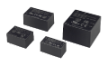
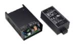
Baseplate Cooling & Cover Structure:
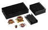
Unlike other regular power supplies, the most notable feature of CFM500M/S is that it can direct the amount of heat energy to the bottom due to the baseplate-cooling design. You may see the difference from the photos below. In general, it may take more time for people using others to solve the heat dissipation issue. However, Cincon optimizes the heat dissipation technology of CFM500M/S by directing the heat to the bottom which is the system’s case. The CFM500M/S could save users from the trouble of dealing with the heat dissipation which may have a greater chance to shorten users’ development time.
Others

Cincon CFM500M/S

Below are the standard derating curves of CFM500M/S under the natural convection condition.


CFM500M/S

Based on the data of CFM500M/S, under the ambient temperature 40℃ (Natural Convection) with different conditions:
1. Input voltage 115Vac, output voltage 12Vdc, and output power would be 300W.
2. Input voltage 230Vac, output Voltage 48Vdc, and output power would be 440W.
CFM500M/S-C

Based on the data of CFM500M/S-C, under the ambient temperature 40℃ (Natural Convection) with different conditions:
1. Input voltage 115Vac, output Voltage 12Vdc, and output power would be 340W.
2. Input voltage 230Vac, output voltage 48Vdc, and output power would be 490W.
The output power could be more while the CFM500M/S are installed on the case of the user’s device or an aluminum plate. The following are the experiments tested under natural convection condition. You may find the outstanding performance of baseplate-cooling.
1.CFM500M/S is screwed on an aluminum plate with the size of 480 x 248 x 1.2mm to simulate the test which is run on user’s device.

Input V: 115 Vac, Output V: 12Vdc, and Ambient Temperature 40 to 70℃ (Natural Convection)
| Part Number | CFM500M/S | |||
| Rated Power | 410W | 380W | 340W | 300W |
| Ambient | 40℃ | 50℃ | 60℃ | 70℃ |
| Input EMI FILTER | 93.7 | 96.8 | 102.6 | 109.6 |
| PFC Inductance | 103.3 | 105.7 | 109.9 | 116.2 |
| PFC MOS | 95.5 | 101.8 | 108 | 114.8 |
| PFC FILTER CAP. | 95.8 | 97.6 | 99.6 | 110 |
| PFC DIODE | 96.9 | 104.9 | 112 | 119.6 |
| LLC MOS | 100.7 | 105 | 110.1 | 119.1 |
| LLC DRIVER | 98.4 | 102.3 | 107.2 | 111.2 |
| BRIDGE DIODE | 92.7 | 98.7 | 105.5 | 110.9 |
| Transformer | 121.9 | 124 | 122.2 | 127.9 |
| Output SR DRIVER | 124.7 | 120.7 | 107.4 | 124 |
| Output SR MOS | 96 | 108.6 | 107.7 | 117 |
| Output Pi FILTER | 100.6 | 108.6 | 107.4 | 106.8 |
| Output Cap.1 | 98.4 | 99.3 | 101.2 | 103 |
| Output Cap.2 | 88.5 | 91.4 | 98.4 | 105 |
| Output Cap.3 | 82.7 | 86.9 | 90.5 | 94.8 |
Input V: 230 Vac, Output V: 48Vdc, and Ambient Temperature 40 to 70℃ (Natural Convection)
| Part Number | CFM500M/S | |||
| Rated Power | 500W | 500W | 475W | 410W |
| Ambient | 40℃ | 50℃ | 60℃ | 70℃ |
| Input EMI FILTER | 68.2 | 76.8 | 84 | 90.5 |
| PFC Inductance | 90.6 | 98.8 | 102.7 | 106.4 |
| PFC MOS | 92.9 | 101.9 | 107.9 | 112.8 |
| PFC FILTER CAP. | 76.3 | 85 | 89.2 | 92 |
| PFC DIODE | 66.3 | 75.9 | 81.8 | 87.3 |
| LLC MOS | 105.7 | 116.1 | 118 | 119.9 |
| LLC DRIVER | 93.2 | 103.1 | 107.2 | 110.8 |
| BRIDGE DIODE | 82.7 | 91.3 | 97.3 | 101.7 |
| Transformer | 116.6 | 125 | 121.9 | 120.4 |
| Output SR DRIVER | 95.8 | 105.6 | 107.7 | 109.9 |
| Output SR MOS | 84.2 | 94.2 | 98.1 | 101.8 |
| Output Pi FILTER | 79 | 88.5 | 92.1 | 95.7 |
| Output Cap.1 | 75.8 | 85.3 | 87.5 | 90.7 |
| Output Cap.2 | 73.6 | 83.7 | 89.6 | 93.2 |
| Output Cap.3 | 67 | 75.8 | 80.7 | 84.9 |
Now you may see the component temperatures are under the limitation. Screwing the CFM500M/S on the aluminum plate would let the output power reach to 410W under the higher temperature of 70℃ due to the benefit from the baseplate-cooling design. In addition, for the experiment of the CFM500M/S with 12Vdc output and the highest output current in this series, it could still have the output power of 300W under the stricter condition of 115Vac input and 70℃.
2. CFM500M/S-C is screwed on an aluminum plate with size of 480 x 248 x 1.2mm to simulate the test which is run on user’s device.

Input V: 115 Vac, Output V: 12Vdc, and Ambient Temperature 40 to 70℃ (Natural Convection)
| Part Number | CFM500M/S-C | |||
| Rated Power | 420W | 390W | 350W | 310W |
| Ambient | 40℃ | 50℃ | 60℃ | 70℃ |
| Input EMI FILTER | 95.9 | 99 | 99.2 | 107 |
| PFC Inductance | 91.2 | 95.4 | 97.7 | 102 |
| PFC MOS | 102.2 | 106.2 | 108.4 | 112.9 |
| PFC FILTER CAP. | 106 | 107 | 107.5 | 107 |
| PFC DIODE | 107.5 | 111.2 | 113.4 | 117.7 |
| LLC MOS | 109 | 112.3 | 113.4 | 117.4 |
| LLC DRIVER | 101 | 104.4 | 106.3 | 110.5 |
| BRIDGE DIODE | 102.3 | 105.6 | 107.5 | 112.1 |
| Transformer | 114.2 | 116.5 | 116.7 | 118.9 |
| Output SR DRIVER | 124 | 124 | 121.8 | 124 |
| Output SR MOS | 118 | 116.6 | 114.9 | 117.6 |
| Output Pi FILTER | 104.5 | 105.7 | 105.1 | 107.1 |
| Output Cap.1 | 102 | 104 | 102.9 | 95.9 |
| Output Cap.2 | 97.3 | 103.5 | 102.7 | 104 |
| Output Cap.3 | 88.6 | 92.1 | 92.7 | 94.6 |
Input V: 230 Vac, Output V: 48Vdc, and Ambient Temperature 40 to 70℃ (Natural Convection)
| Part Number | CFM500M/S-C | |||
| Rated Power | 500W | 500W | 500W | 430W |
| Ambient | 40℃ | 50℃ | 60℃ | 70℃ |
| Input EMI FILTER | 79.6 | 88.8 | 92.9 | 97.6 |
| PFC Inductance | 83.5 | 92.9 | 97.5 | 101.1 |
| PFC MOS | 91.8 | 101.4 | 107.8 | 112.9 |
| PFC FILTER CAP. | 85.4 | 94.9 | 98.2 | 98.7 |
| PFC DIODE | 70.5 | 79.6 | 87.5 | 92.6 |
| LLC MOS | 104.4 | 115.3 | 116.8 | 118.6 |
| LLC DRIVER | 92.6 | 103 | 107.2 | 110.6 |
| BRIDGE DIODE | 83.8 | 93.3 | 99.6 | 104.1 |
| Transformer | 108.1 | 117.9 | 117.4 | 117 |
| Output SR DRIVER | 97.4 | 107.5 | 109.1 | 110.5 |
| Output SR MOS | 84.6 | 94.9 | 99.2 | 102.6 |
| Output Pi FILTER | 80.9 | 90.5 | 94.8 | 97.5 |
| Output Cap.1 | 82.9 | 92.3 | 96.6 | 97.6 |
| Output Cap.2 | 84.6 | 94.5 | 97.9 | 99.5 |
| Output Cap.3 | 70.6 | 80.1 | 85.8 | 88.8 |
Now you may see the component temperatures are under the limitation. Screwing the CFM500M/S-C on the aluminum plate would let the output power reach to 430W under the higher temperature of 70℃ due to the help of the baseplate-cooling design and the cover. In addition, for the experiment of the CFM500M/S-C with 12Vdc output and the highest output current in this series, it could still have the output power of 310W under the harsher condition of 115Vac input and 70℃.
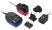
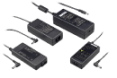
Installation Instruction:
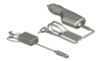
The CFM500M/S have the mechanical design to be fixed on a metal plate or on the surface of the user system case which could have a faster and more efficient conduction for heat dissipation. There are three ways to screw the power supply, increasing the flexible choices of installation.


Mechanical Specification:
| Baseplate | Cover |
 |
 |
Conclusion:
The CFM500M/S series provide 500W output power with the compact size of 3” x 5”. The baseplate cooling design makes this series achieve the higher power density and improves the heat dissipation performance under fanless condition and higher ambient temperature. Furthermore, the CFM500M/S offer an additional 12Vdc fan output pin with the protection to keep the main output operating stably while the connected fan runs into the situation of malfunction and short circuit.
Forced Air Flow Curve below shows the CFM500M/S could work at 500W with a 21CFM fan. Whether or not to use a fan still depends on the system environment. Some users evaluate the situation that it is accepted for them to use CFM500M/S under fanless condition. Nevertheless, the CFM500M/S series show the flexibility, stability, and reliability in different system environments with various setup options, such as baseplate type, cover type, or either one connected with a fan.

Product Page:CFM500M & CFM500S
Contact for more support: sales@cincon.com.tw